
Description
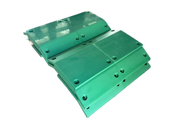
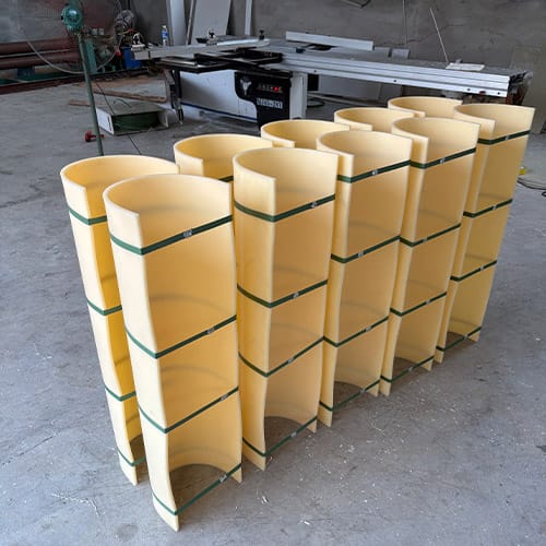
UHMWPE U-trough liners are curved wear components fitted inside screw troughs, chutes, channels, and other bulk-material paths. Their performance depends on an accurate trough cross-section, continuous support, controlled joints, suitable fasteners, and a liner grade matched to the conveyed material. A dual-color construction can make wear-through visible, but only when the color layers and inspection rule are defined in the purchase specification.
This page is intended for replacement segments and new liner systems manufactured from a confirmed drawing. It is not a generic flat-sheet page: the installed radius, segment sequence, material-flow direction, and fastening arrangement are central to the order.
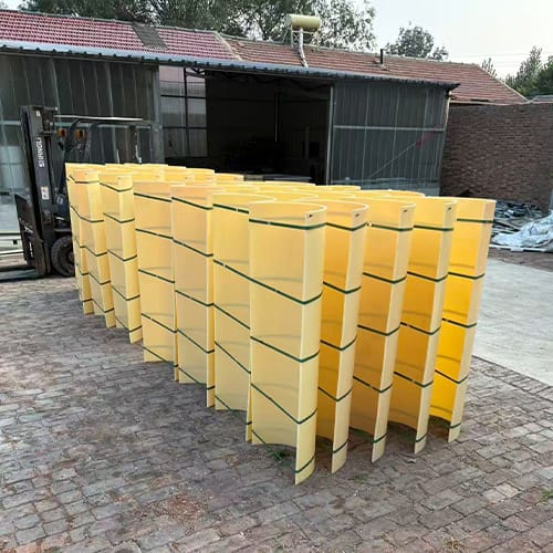
Start with the steel trough, not the worn liner
Measure the supporting trough at several positions and record its internal profile. A nominal diameter may not describe a trough with straight side walls, multiple radii, a flattened bottom, weld distortion, or a tapered section. Supply a cross-section drawing with datums, included angle, radii, straight lengths, and the location of supports and obstructions.
An old liner helps identify holes and segment lengths, but it may have relaxed, worn thin, stretched around fasteners, or changed shape after removal. Use the steel structure and installation envelope as the primary references. Mark any local transition near inlets, outlets, access covers, bearings, or screw supports rather than assuming one profile fits the full conveyor.
Map the conveyed material and wear zones
Describe the bulk solid by particle size, shape, hardness if known, moisture, contamination, temperature, and tendency to pack or bridge. Also provide conveying speed, feed rate pattern, start-stop frequency, and whether material drops onto the liner from height. Sliding abrasion along the trough differs from concentrated impact below a feed point.
Photographs of the existing wear pattern can reveal where material loads the system. Polished tracks, grooves, local thinning, damaged joints, and elongated fastener holes point to different design questions. Record the position of each observation on the conveyor layout so the liner thickness, joint arrangement, or protection around impact areas can be reviewed deliberately.
How dual-color wear indication should be specified
In a dual-color liner, the working surface has one color and the underlying layer has a contrasting color. When the lower color first becomes visible, maintenance teams gain a clear inspection signal that the working layer has been penetrated at that location. This is useful for locating non-uniform wear that may otherwise be difficult to see.
The second color does not automatically state how much service life remains. A meaningful replacement rule requires the approved total thickness, working-layer thickness, lower-layer thickness, measurement location, acceptable exposed area, and consequence of continued operation. If those values are not agreed, the color change should be treated as an inspection trigger rather than a calibrated life gauge.

Segment length and installation sequence
Segment length should suit handling access, trough geometry, support spacing, fastener layout, and installation sequence. Long segments reduce the number of joints but may be harder to form, transport, position, and replace inside confined equipment. Short segments are easier to handle but create more joints that must be protected from the material stream.
Create a position schedule for the full trough. Give every segment a unique number and show its orientation, upstream and downstream ends, length, cross-section, and hole pattern. Labels should remain readable until installation. A controlled sequence is especially important where profiles change along the conveyor or where left- and right-hand parts look similar.
Design joints around material-flow direction
A liner joint should not present an exposed edge that the conveyed material can lift or catch. Show the normal flow direction on every drawing and define whether joints are butted, overlapped, stepped, or otherwise detailed. The correct arrangement depends on the liner construction, trough access, particle behavior, and whether the conveyor ever reverses.
End clearance must also consider installation temperature and operating temperature. The designer should decide how thermal movement is accommodated without opening a harmful gap, forcing one segment over another, or loading the fasteners. Avoid specifying zero clearance unless the complete expansion and installation condition has been evaluated.
Fastening details need a complete drawing
Fasteners keep the liner seated against the trough and prevent the material stream from entering underneath. The drawing should identify fastener type, hole diameter, recess geometry, washer or backing arrangement, edge distance, pitch, and tightening method. Fastener heads or plugs should not project into the conveyed material path unless that exposure is intentional.
- Show all holes from common datums rather than dimensioning a chain of hole-to-hole distances.
- Identify slotted holes or movement allowances and state their orientation.
- Define countersinks, counterbores, plugs, or caps with finished depths and diameters.
- Keep critical holes away from thin edges and joint transitions unless the design has been reviewed.
- Provide access information for installation and later replacement of concealed fasteners.
UHMWPE U-trough liner specification table
| Liner input | Information to provide | Design consequence |
|---|---|---|
| Trough profile | Internal cross-section, radii, angle, straight sides, taper, and datums | Controls liner fit and contact with the support |
| Conveyed material | Particle size, shape, moisture, contaminants, temperature, and impact | Supports grade and wear-pattern review |
| Liner construction | Total thickness, working layer, contrasting layer, and approved colors | Defines the physical meaning of the wear indicator |
| Segments | Length, quantity, position number, orientation, and handling limit | Controls installation sequence and replacement access |
| Joints | Flow direction, overlap or butt detail, clearance, and transition shape | Reduces edge exposure and material ingress |
| Fastening | Fastener type, pitch, holes, recesses, backing, and access | Keeps the liner seated without obstructing flow |
| Environment | Operating and installation temperature, chemicals, washdown, and outdoor exposure | Supports material and expansion review |
| Acceptance | Drawing revision, fit template, layer check, labels, and inspection records | Creates a repeatable receiving standard |
Temperature, cleaning, and chemical exposure
Provide the minimum installation temperature, normal operating range, temporary excursions, and any heat from the conveyed product or adjacent equipment. Temperature affects dimensions, fit, and material behavior. The supporting structure and fastening arrangement should be reviewed for the same range rather than treating the liner in isolation.
List washdown chemicals, oils, process liquids, and cleaning temperature. Chemical compatibility depends on the exact formulation, concentration, contact time, stress, and temperature. Where a documented regulatory or process requirement applies, identify it before material approval and retain evidence for the grade actually supplied.
Installation and commissioning checks
Before installation, confirm segment numbers against the layout and inspect the steel trough for burrs, projections, damaged welds, trapped debris, and dimensional changes. Dry-fit critical transitions where practical. The liner should seat against its intended support without being forced into an incorrect radius or bridging an unrecorded obstruction.
After fastening, check joint direction, edge seating, recess depth, segment clearance, and screw or conveyor-component clearance through a complete manual rotation or approved commissioning process. Document the new liner condition and visible color before service; this creates a baseline for future wear inspections.
Plan inspections around the color transition
Inspection points should include feed zones, changes in trough direction, joints, fasteners, and areas where previous liners wore fastest. Clean the surface sufficiently to distinguish actual layer exposure from transferred material or staining. Record exposed-color location and area consistently so changes can be compared over time.
Replacement timing should consider remaining liner thickness, exposed support risk, fastener condition, process consequence, and maintenance access. The contrasting layer is one input to that decision. It should complement thickness checks and equipment inspection, not replace them.
Related UHMWPE supply and machining options
Customers producing their own profiles can review UHMWPE plastic sheet supply. Segments requiring controlled holes, recesses, transitions, or non-standard end shapes can be discussed through the CNC milling plastic parts service. For U-trough projects, the liner layout and cross-section drawing remain the controlling production documents.
Request a trough-specific technical review
Send the trough cross-section and layout, segment schedule, material-flow direction, conveyed-material details, operating temperature, current wear photographs, required color-layer construction, fastening drawing, quantity, and inspection requirements. SDYZ Plastic can then review the UHMWPE liner as an installed wear system rather than as a simple curved sheet.
Frequently asked questions
What dimensions are needed for a UHMWPE U-trough liner?
Provide the internal trough cross-section, radius or multiple radii, included angle, straight-side dimensions, liner thickness, segment length, joint layout, support condition, and fastening positions.
What does the second color in a dual-color trough liner indicate?
The contrasting layer can provide a visible sign that the working layer has worn through. It is not a calibrated remaining-life measurement unless layer thickness, inspection location, and replacement criterion are defined.
Should liner joints face with or against material flow?
Joint design should prevent the conveyed material from catching an exposed edge. The correct overlap or joint orientation depends on flow direction, trough geometry, installation sequence, and whether material can reverse.
Can UHMWPE U-trough liners be supplied as replacement segments?
Yes, subject to drawing review. Measure the steel trough as well as the old liner because worn or distorted segments may not represent the intended installed geometry.
What operating information is required for material review?
State the conveyed material, particle size and shape, contamination, moisture, temperature, speed, feed pattern, impact zones, cleaning chemicals, and current wear pattern.