
Description
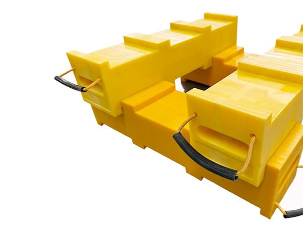
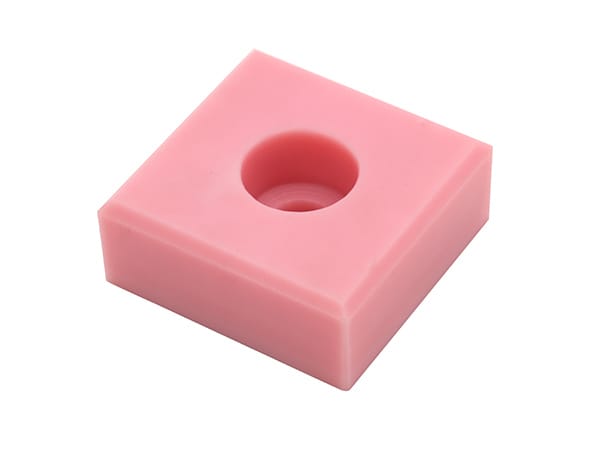
A UHMWPE plastic cushion block is a custom-machined contact, wear, spacer, or stop component fitted between moving equipment and a supporting structure. The word “cushion” describes its position or protective role; it does not make UHMWPE equivalent to rubber or another elastic shock absorber. Correct selection requires a drawing, defined interfaces, load direction, contact conditions, installed clearance, and an understanding of what the machine must do when contact occurs.
Typical inquiries involve replacement blocks, sliding contact pads, guides, bump stops, support pieces, and sacrificial components intended to protect a more expensive metal assembly. Because these duties differ, no universal load rating or impact capacity should be assigned from the product name alone.
Define the block's job inside the machine
Begin by identifying the two surfaces connected by the block. State which surface moves, which surface supports the part, where force enters, and whether contact is continuous, intermittent, sliding, or caused by an end-of-travel event. A block that guides a moving frame has different acceptance criteria from one that only establishes spacing during assembly.
Describe the consequence of wear or movement. If wear changes alignment, opens an unsafe gap, allows metal-to-metal contact, or affects product quality, the replacement threshold and inspection points should be visible in the maintenance plan. If the block is non-critical and easily replaced, simpler dimensional controls may be sufficient.
UHMWPE is not an elastomeric damper
UHMWPE is an engineering thermoplastic with useful wear and low-friction characteristics in appropriate applications, but it does not deform and recover like a rubber spring. A UHMWPE block may spread contact over an area, provide a replaceable face, or reduce direct metal contact. It should not be credited with a specific stopping distance or absorbed energy unless the full mechanism has been engineered and tested.
Where a moving mass repeatedly strikes the block, provide mass, speed, impact direction, frequency, surrounding stiffness, allowable travel, and any existing spring, hydraulic, or elastomeric damping. The equipment designer must determine whether UHMWPE is suitable as the contact element and whether another energy-control component is required.
Map the working face and load path
Mark the working face, mounting face, and load direction on the drawing. A force aligned through the supported thickness is different from a side load that tends to shear the fasteners or peel the block away from its bracket. Show the support area behind the block and any unsupported projection beyond the mounting surface.
Provide the expected contact footprint rather than only the total force. A narrow edge, bolt head, roller, or misaligned plate can create concentrated pressure and local damage. If the mating component changes position during operation, show its contact path across the block.

Use machine datums for replacement measurements
A removed sample is valuable, but it should not be treated as a perfect master. Compression marks, polished areas, mushroomed edges, elongated holes, cracks, and permanent distortion can change the measured dimensions. Compare the sample with machine datums, bracket spacing, bolt locations, and the intended operating clearance.
When no original drawing exists, photograph the installed part before removal and mark its orientation. Measure the mounting interface first, then the working face position. Record any shims, washers, backing plates, or adjustment slots because these may explain why the old block does not match the apparent opening.
Mounting holes and recesses require detail
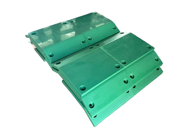
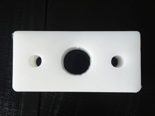
The hole pattern should restrain the block without creating local stress or allowing fastener heads to interfere with the moving component. Dimension holes from common datums and identify clearance holes, slots, counterbores, countersinks, threaded inserts, plugs, or backing hardware. State whether holes are drilled through or stop at a controlled depth.
- Keep holes and recesses far enough from edges for the intended load and installation method.
- Show slot direction where thermal movement or adjustment is expected.
- Define the finished depth of recessed fasteners relative to the working surface.
- Identify the tightening procedure and hardware responsible for retaining the block.
- Provide tool access for initial installation and future replacement.
Allow for fit, temperature, and movement
Installed clearance should be specified at a stated temperature where it affects machine travel or alignment. Plastic and metal components do not necessarily change dimension at the same rate. Long blocks, constrained mounting, broad temperature ranges, and close-running gaps require particular attention to movement and fastening.
Do not force an oversized block into a steel pocket or clamp it without considering dimensional change. If the block must slide during adjustment, identify the sliding faces and required clearance. If it must remain fixed, show how movement is controlled without relying on an unspecified bolt torque.
UHMWPE cushion block specification table
| Design question | Required information | Reason for review |
|---|---|---|
| Function | Stop, guide, spacer, wear face, support, or another defined duty | Establishes what successful operation means |
| Interfaces | Working face, mounting face, mating materials, and support area | Defines the contact and load path |
| Loading | Direction, force, footprint, speed, frequency, and impact if present | Supports material and geometry review |
| Geometry | Overall size, profiles, radii, chamfers, slots, pockets, and datums | Creates a manufacturable finished-part drawing |
| Fastening | Hole pattern, recesses, hardware, backing, access, and tightening method | Controls retention and working-face clearance |
| Installation | Operating clearance, position, orientation, shims, and adjustment range | Prevents fit and alignment errors |
| Environment | Temperature, moisture, chemicals, debris, outdoor exposure, and cleaning | Supports UHMWPE grade review |
| Acceptance | Critical dimensions, labels, fit check, surface condition, and inspection records | Provides a repeatable basis for receiving |
Read failure marks before ordering the replacement
The old block can show whether the problem is ordinary surface wear or a system issue. One-sided polishing may indicate misalignment. Elongated holes can indicate movement at the fasteners. Cracks near recesses may point to local stress, insufficient edge distance, overtightening, or unexpected impact. A crushed corner may show that the contact face is smaller than expected.
Photograph the damage before cleaning and again after cleaning. Include the mating metal component and bracket. Replacing the block with the same geometry may be reasonable when wear is expected and controlled; repeated premature damage should trigger review of alignment, load path, speed, hardware, and operating sequence.
Position control for sets of machine blocks
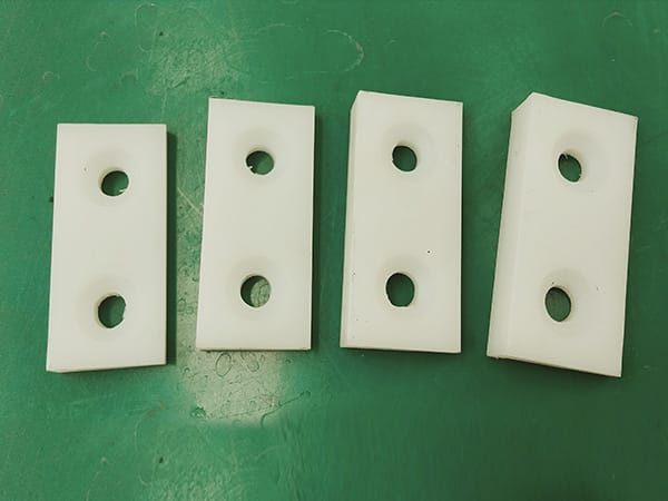
Machines often use several blocks that appear similar but differ in hole position, thickness, orientation, or working-face angle. Assign a part number and installation position to each geometry. Engraved identifiers or durable labels can be added where they do not interfere with contact or weaken a critical section.
For repeat orders, maintain one approved drawing revision for each position and avoid combining unlike parts under a single generic description. Packing should keep identified parts separated so maintenance teams can install them without measuring every block on site.
Inspection and replacement criteria
After installation, verify fastener seating, working-face position, movement clearance, and contact alignment through an approved commissioning procedure. Establish a baseline measurement or photograph for the new part. The maintenance inspection should look for wear depth, looseness, cracks, edge damage, hole elongation, heat damage, or transferred metal.
Replacement criteria should connect the observed condition to machine function. Examples include minimum remaining thickness, maximum clearance, loss of alignment, exposed hardware, or visible cracking, but the actual limits must come from the equipment owner or designer. The product page does not replace a machine-specific safety assessment.
Related material and custom-machining options
For customers who need raw stock before designing the component, review UHMW PE sheet for industrial wear parts. Blocks with complex pockets, profiles, recesses, or controlled hole patterns can be discussed through the CNC milling plastic parts service. The finished cushion block should always be ordered from its own controlled drawing.
Send a machine-specific inquiry
Provide the block drawing, photographs in the installed position, machine function, mating surfaces, load direction, contact conditions, operating speed, temperature, current failure marks, material requirement, quantity, and inspection criteria. SDYZ Plastic can then review raw material and machining requirements without treating the block as an outrigger pad, generic sheet, or unspecified shock absorber.
Frequently asked questions
Is a UHMWPE cushion block the same as a rubber shock absorber?
No. UHMWPE is a comparatively rigid engineering plastic, not an elastomer. A block may protect a contact surface or serve as a wear component, but energy absorption and stopping performance require system-level engineering.
What load information is needed for a custom cushion block?
Provide load direction, maximum force if known, contact area, impact speed or frequency, support condition, allowable movement, temperature, and the consequence of excessive deflection or failure.
Can a worn block be copied without a drawing?
A sample can help, but dimensions should be checked against the machine interfaces. Wear, creep, elongated holes, and impact damage may make the removed block different from its original shape.
Which dimensions are most important on the drawing?
Identify overall size, working face, mounting-face flatness, hole pattern, recesses, slots, edge radii, alignment datums, installed clearance, and any position-specific features.
Can position numbers be machined into multiple blocks?
Yes, subject to drawing review. Position labels, orientation marks, and part numbers can reduce installation errors when several similar blocks belong to different machine locations.