



Description
An HDPE plastic grate is a machined or fabricated cover with openings that allow liquid, air, or selected debris to pass while the remaining ribs span a supported opening. Correct specification starts with the opening to be covered, the support ledge, the unsupported span, the load case, and the required flow path. Outside dimensions alone are not enough to establish whether a grate is suitable.
This page applies to custom drainage covers, equipment guards, tank or channel covers, removable access panels, and other open-pattern HDPE components. Each design must be evaluated for its own installation. The words “HDPE grate” do not create a universal load rating, pedestrian rating, or vehicle rating.
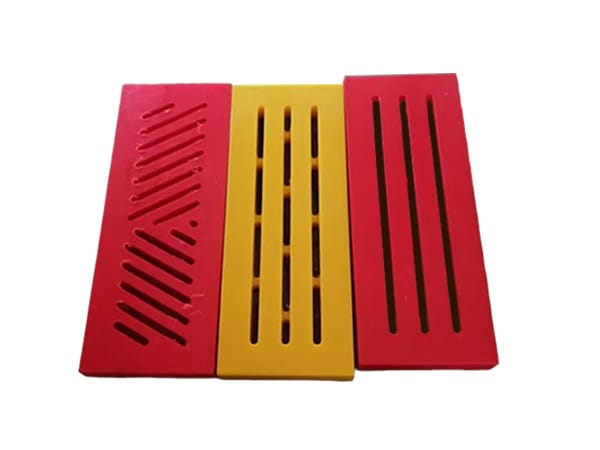
Define the opening and support ledge first
The grate must sit on a known support geometry. Record the clear opening below the grate, the overall frame size, the bearing width available on each side, and any interruption caused by corners, pipes, hinges, or fasteners. If the support is not continuous, show the position of every beam or ledge. The largest unsupported distance often governs the structural review.
For a recessed cover, include the recess depth and the required finished elevation. A grate that sits too high can create an obstruction; one that sits too low can collect residue or become difficult to lift. Where several panels cover a long channel, show joint positions and identify whether neighbouring panels share a support.
Open area is a flow and retention decision
A larger percentage of open area may improve passage through the panel, but it also changes rib width and stiffness. The opening pattern should be chosen from the required liquid flow, debris size, cleaning method, and items that must not fall through. Narrow slots, round holes, square apertures, and wider channels behave differently in service and during cleaning.
When drainage is the priority, provide expected flow direction and describe whether solids, fibres, chips, food particles, or other material may reach the grate. A pattern that passes clean water may clog in a process stream carrying solids. If the panel functions mainly as a guard, the maximum permissible opening may matter more than the total open area.
Load case, span, and deflection must be reviewed together
State exactly what may contact the cover: maintenance tools, containers, distributed material, a wheel, a foot, or only its own weight. Give the maximum expected load, contact area, location, duration, frequency, and any impact. A concentrated load near the centre of a rib is different from an evenly distributed load over the entire panel.
Allowable deflection should be agreed with the equipment designer. Excessive movement can feel unstable, interfere with nearby parts, change drainage slope, or cause the panel to leave its support. If people or vehicles may cross the grate, the buyer must identify applicable safety and engineering requirements before manufacture. Material selection cannot replace a complete load and installation assessment.

Choose rib orientation to match the supports
Ribs should transfer load to the support rather than terminate across an unsupported direction. Mark the span direction on the drawing and identify the top face. If the panel can be installed in more than one orientation, add a permanent orientation mark or make the geometry asymmetric so incorrect placement is less likely.
Corners around openings deserve particular attention because sharp internal corners can concentrate stress. Radius details, rib intersections, edge distance, and remaining material around lifting holes should be shown on the drawing. Machining feasibility and structural adequacy are separate checks; a feature that can be cut is not automatically suitable for the load.
Installation options for removable and fixed covers
- Drop-in panel: define bearing ledges, lifting access, clearance, and how the panel is prevented from shifting.
- Bolted cover: specify hole positions, fastener type, washer area, tightening method, and service access.
- Hinged access cover: show hinge loads, open position, latch details, and the frame interface.
- Multi-panel channel: identify panel sequence, shared supports, joint clearance, and position labels.
- Equipment guard: define the hazard boundary, permissible opening, mounting distance, and responsible design standard.
Thermal movement and installation clearance should be considered where the service temperature changes significantly or the panel is long. Fasteners should restrain the component without creating damaging point pressure. Do not force an oversized panel into a frame; verify the opening and drawing before adjusting the finished part on site.
Environment and chemical exposure
List the liquids, cleaning chemicals, oils, process residues, and temperatures that may contact the grate. Chemical compatibility depends on concentration, exposure time, temperature, stress, and the exact HDPE grade. A general compatibility statement should not replace review of the actual service mixture.
For outdoor installations, identify sunlight exposure, ambient temperature range, standing water, freeze-thaw conditions, and the required service period. Where fire performance, electrical behavior, hygiene, or another regulated property matters, state the required standard and evidence before material approval. Unpublished performance should not be assumed from appearance.
HDPE plastic grate design checklist
| Design input | Information required | Effect on the grate |
|---|---|---|
| Opening to cover | Clear length and width, frame size, recess depth, and obstructions | Establishes the true installation envelope |
| Support | Bearing width, beam positions, edge supports, and maximum unsupported span | Defines how the ribs transfer load |
| Flow requirement | Liquid or air path, expected solids, direction, and cleaning access | Guides aperture pattern and open area |
| Load case | Load magnitude, footprint, location, duration, frequency, and impact | Provides the basis for structural review |
| Panel geometry | Thickness, rib width, aperture size, radii, and top-face orientation | Controls stiffness, retention, and manufacturability |
| Installation | Drop-in, bolted, hinged, multi-panel, or another defined arrangement | Determines holes, clearances, and handling features |
| Environment | Temperature, chemicals, UV exposure, moisture, and cleaning method | Supports grade and service-condition review |
| Acceptance | Drawing revision, fit checks, deflection criterion, labels, and documents | Creates an inspectable purchase specification |
Cleaning and maintenance access
A drainage cover should be removable or cleanable without creating an unsafe handling task. Define lifting slots, hand access, panel weight limits, and the space available to remove the grate. If the underside collects residue, the maintenance plan should include access to both faces and the supporting frame.
Inspection should look for cracks, damaged ribs, permanent bowing, worn supports, loose fasteners, blocked apertures, or movement in the frame. The site owner should decide inspection frequency from exposure and consequence of failure. A damaged load-bearing cover should be taken out of service and assessed under the site’s safety procedure.
How to measure a replacement plastic grate
Use the frame as the primary reference, then compare it with the removed panel. Measure the clear opening, support ledge, recess, and panel thickness at several points. Photograph the installed orientation and mark which face is uppermost. If the old grate has bowed, cracked, or worn at its bearing edges, record those conditions instead of copying them into the new geometry.
For a series of panels, assign each position a unique identifier and note any dimensional differences. One nominal channel width may contain local variations around outlets or equipment. A position schedule reduces the risk of delivering several similar panels that cannot be exchanged during installation.
Related HDPE and machining capabilities
Projects beginning with raw material can review HDPE plastic sheet supply. Grates that require pockets, repeated apertures, counterbores, or complex perimeter shapes can also be discussed through the CNC milling plastic parts service. The final grate drawing should remain the controlling document for production and inspection.
Request a drawing-based review
Submit the opening and frame drawing, panel dimensions, support spacing, aperture pattern, load case, environment, installation method, quantity, and acceptance criteria. For a replacement, include photographs of the frame and failed or worn areas. SDYZ Plastic can use that information to review material supply and machining scope without treating the grate as an ordinary cut sheet.
Frequently asked questions
What information is needed to design an HDPE plastic grate?
Provide the clear opening, support ledge, unsupported span, load type, opening pattern, drainage requirement, environment, fastening method, quantity, and applicable acceptance criteria.
Can an HDPE plastic grate support pedestrian traffic?
Do not assume pedestrian suitability from the material name. The complete grate geometry, support span, installation, expected load, deflection limit, slip conditions, and applicable local requirements must be evaluated.
How is open area selected for a plastic grate?
Open area should balance liquid or debris passage with rib strength, object-retention requirements, cleanability, and the size of anything that must not pass through the cover.
Can a replacement grate be made from the old part?
A sample helps, but the opening and support frame should also be measured. A damaged or distorted grate may no longer represent the intended geometry.
Can fixing holes or lifting slots be machined into the grate?
Yes, when the drawing defines their dimensions and positions. Features near ribs or edges should be reviewed so they do not weaken critical sections.